Equalizers tutorial
In this tutorial we cut through the confusion surrounding equalizers by focusing on the different types of EQ devices and highlighting the pros & cons of each.
Spectral information in audio signals
(let's start with some theory...)An audio signal is usually displayed as a graph that shows time in the horizontal axis, and an amplitude value in the other. This is called a time-domain graph as it exhibits how a signal changes over time. However, this isn't how our brain actually perceives sound. Instead, we split the incoming signal into millions of frequencies (so-called sine waves), and each of these frequencies are either played or not at any given moment. This is called the spectral, or frequency, domain. Using this method, our brains not only decode and understand the overall sound, but can also distinguish between each individual sound source (e.g. each musical instrument), as easily as if each was playing solo. This is because most sounds have a unique 'fingerprint'.
For example if we press A2 on a Hammond organ, it plays an 800 Hz sine wave as the 'fundamental frequency'. The organ is designed to add so-called 'higher harmonics', multiples of the fundamental frequency (which can be referred to as the first harmonic). In this example, the second harmonic is 1600 Hz, the third is 2400 Hz and so on. If you look at the resulting signal, you probably wouldn't be able to recognize anything about it except its peak levels, but our brain can easily decode the frequencies and find a pattern that it recognizes as a Hammond organ (or, rather, as a sound it associates with the label "Hammond organ").
Sound can be viewed as a huge number of frequencies. Each of these component frequencies has a volume (0 or -infinity dB if it is not present) and also a phase (how the particular sine wave is moved in time).
Our brain is able to ignore this phase. You can check this yourself by simply delaying a signal by just a millisecond. Does it sound different? Not at all, even though you have actually shifted phase of all frequencies in the sound. And that's not all, you have also shifted each individual frequency by a differing amount because each is repeating at a different rate. So sonically, you have made a huge mess of the phase content of the audio, but you cannot hear it! But please note that the brain still detects phase, and is sensitive to small differences in phase between each ear, which we will cover later.
Now, what has this got to do with equalizers? Equalizers are tools that can manipulate the volume of the individual frequencies that make up a sound. You may have heard the term 'filter'? Well, that's exactly the same, an equalizer is a special type of filter. Enough of the theory for now, let's talk about the various types of equalizers.
Graphical equalizers
Probably one of the earliest designs, this type of equalizer has a fixed number of bands, generally at fixed frequencies. Each band has a gain, which lets you amplify or attenuate a predefined range of frequencies. These types of equalizers are often found in hardware units, because the gain sliders are easy to control by hand. Within software applications, they are mostly found in low-end user programs, such as media players, because they are extremely easy to understand. You will rarely use these in mixing or mastering, because this approach is just far too inaccurate. Some have a very high number of bands, but this is usually still not accurate enough.

Note that there is no equalizer, which can amplify only within the range, for example, 100 Hz - 1 kHz. It will always affect the frequencies around the range as well (it will actually affect all frequencies in the signal, but the further it is from the range, the less it is changed).
- Easy-to-use.
- Easy to develop and possibly make linear-phase (see below).
- Very inaccurate.
- Almost no flexibility.
- May generate more processing noise (depending on the algorithm).
Parametric equalizers
Parametric equalizers are extremely flexible but can be harder to understand. Each has a set of fully configurable bands, allowing you to amplify or attenuate a certain range of frequencies, or everything before or after a certain frequency point. The hardware units are usually restricted to professional audio environments, as they are costlier and much harder to use. The software versions however, are widely used and are the main tools for you as an audio engineer.
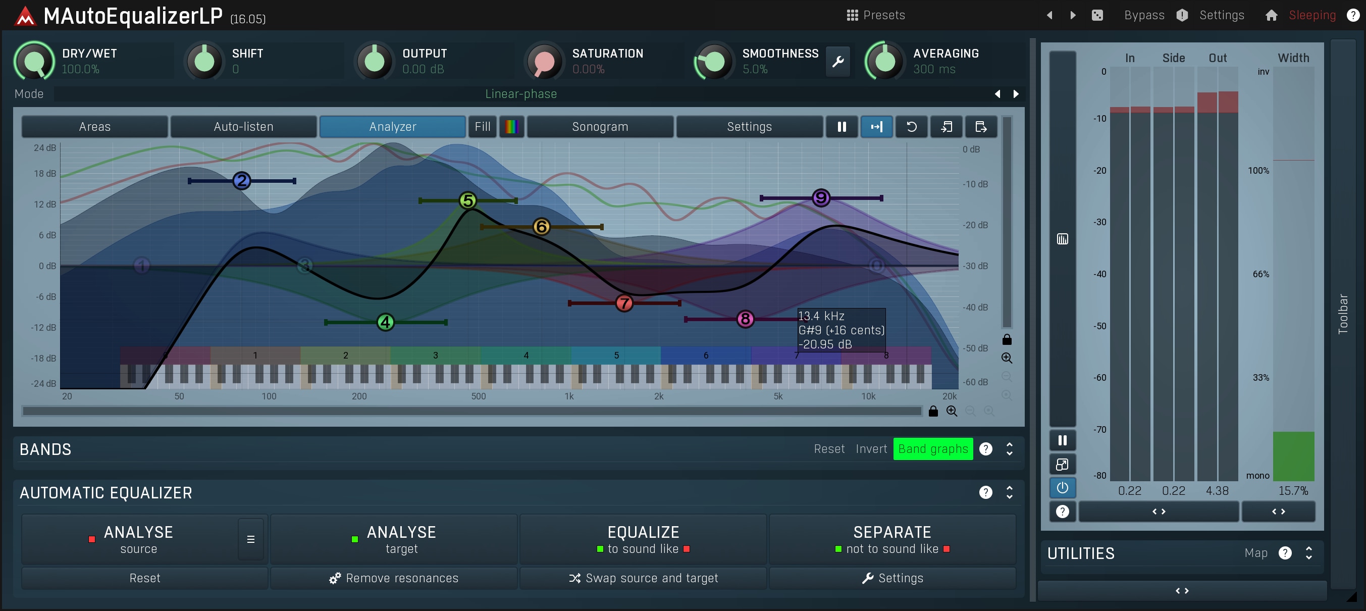
We will cover the basics of parametric equalizers using MAutoEqualizer. Please download the demo version for free, to follow the tutorial and use the integrated analyzer to actually show you what the equalizer does and how it works.
Bands
Each band of the parametric equalizer has at least 4 parameters:
- frequency
- gain
- filter type
- Q
Frequency - its use and meaning depends on the type of filter. For some types, it defines
which frequency is affected the most; for others, it indicates the end of the range that the filter will influence.
Gain - allows amplification or attenuation of a certain range of frequencies.
Filter type and Q are discussed below.
Filter types & usage
Filter type defines the shape of the processing curve, and therefore how each frequency will be affected. There are several standard filter types. We cover the principal ones below. In all cases, the curve in the graphs shows the relative effect on the frequencies.
Peak filter
Peak filter has a typical bell type curve around the central frequency, showing the frequencies affected by the specified gain. These filters are the most commonly used.
For example, a snare drum, usually has its most dominant frequencies somewhere around 1-2 kHz. Using this filter is a matter of finding the frequency and amplifying it. Simply take the band frequency point and slide it across the spectrum. The hardest part is deciding where it sounds best ;).
Low/high shelf filter
Low/high shelf filter affects all frequencies below/above the threshold limit defined by the frequency parameter and the Q value. These are mostly used on bass or treble.
For example, to make a track or even the entire mix 'brighter', just use a high-shelf filter and amplify everything above a certain frequency. Use this effect with caution - adding bass or treble often seems to sound better, however this may just be the 'hi-fi effect'.
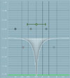
Low/high pass filter
Low/high pass filter lets you remove all frequencies above/below the limit defined by the frequency parameter. Well, apart from some theoretically perfect filters, that's not entirely true but they do attenuate particular frequencies a lot.
For example, you often need to remove bass content from vocals, piano, guitar and other higher pitched tracks, so that sonically, they don't collide with the bass and bass drum. You could use a low-shelf filter, but that would usually let you attenuate by only 24 dB, which may not be enough. Additionally, there is generally no reason to keep 50Hz in an acoustic guitar track, as it is probably only hum and noise. A high-pass filter, can easily remove 80 dB from the frequencies you just don't want. (N.B. the terminology here can be a little confusing, 'high-pass', not 'low-pass', because it lets all frequencies higher than the limit 'pass' though while the others are rejected (extremely attenuated)). Please note that this type of filter does not use a gain parameter as it has no need for it.
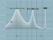
Band-pass and notch filters
Band-pass and notch filters are similar to low/high pass filters as they either remove all frequencies in a specific range around the central frequency (notch) or outside it (band-pass).
For example, you may wish to remove some unwanted noise. It may be some electrical hiss, ambient resonances, or mechanical flaws on drums etc. In most cases these appear on a constant, usually small, frequency range, so you just need to remove them. A band-pass filter will remove everything except the specified range. Slide the central frequency to the point that you hear the noise the most. Then switch to the notch filter. Voila! The notch filter removes the unwanted frequencies that you targeted with the band-pass filter.
Q, alias resonance or band-width
Often called resonance, the Q parameter defines the steepness or width of each filter depending on its type.
The width of the filter, or Q, becomes narrower the higher the number selected. With MAutoEqualizer for example, the Q ranges from 0.05 (widest setting set by placing the value slider fully right) to 20 (narrowest setting set by placing the slider fully left).

Please not that not all Q values are appropriate for all filter types. As an example, if we try using a low pass filter set to a frequency of say 1 kHz with minimal width (Q slider fully to the left, and maximal Q value of 20), we create 'a huge hill' near the 1 kHz band. This is called resonance and is caused by the way the filter works and the physical limitations. What we have tried to do in effect, by specifying minimal width, is to create an extremely steep filter, which is unfortunately not that simple. There are some advanced methods to create steeper filters, but they have other flaws (ripple in the pass-band, post-ringing, instability etc.), which are often unacceptable in audio. This is not a digital audio error, it is simply part of the design and is also present in hardware equalizers. Fortunately, you will rarely need pass/shelf filters to be so steep unless you want to use them as a creative effect.
This is basically the reason why the Q parameter is often referred to as resonance. If you listen to the sound produced by such a filter, it is similar to an object (glass for example), resonating at a particular frequency, making it louder.
Harmonics
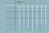
It's natural for a mechanical object to generate harmonics. If it resonates at 2 kHz for example, it is probable that it will generate a harmonic at 4 kHz as well, and then 8 kHz etc. MAutoEqualizer also contains more advanced parameters, such as harmonics control, to overcome this problem. This feature creates duplicates of the original filters at harmonic positions, behind the scenes This may initially sound complicated, but it's actually fairly simple. If we recall using the notch filter to remove some noise, using harmonics control you could create the basic notch filter at 2 kHz and then use harmonics control to let MAutoEqualizer place other notch filters at 4 kHz, and 8 kHz etc.
As you can see, parametric equalizers may be a little harder to understand, but are essential tools that, once mastered, will provide tremendous results. They are currently the best compromise between flexibility, speed of work flow and audio quality.
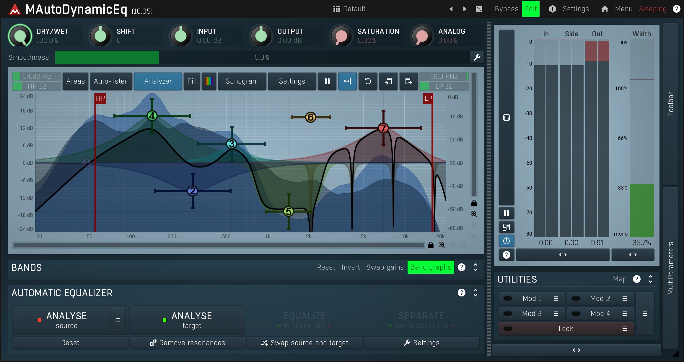
Finally there are dynamic equalizers, which extend parametric equalizers by detecting the input level and reacting with band gains in some way. These have a huge potential as they can do more than traditional equalizers, multiband compressors & expanders, de-essers etc. Probably the most easy-to-use yet versatile ones are MAutoDynamicEq and MDynamicEq.
- Very flexible and powerful.
- Very fast to use once you learn it.
- Very low distortion.
- Very high speed.
- Harder to understand.
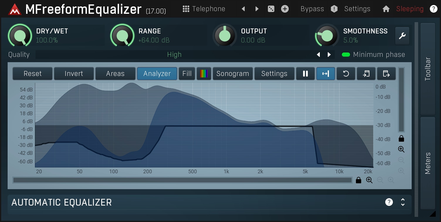
Freeform equalizers
Free form or curve equalizers are designed to let you draw in the frequency response that you want. So if you need a perfect low-pass filter, draw it and it will be available. At least, that's the theory.MFreeformEqualizer is an example of this type of equalizer.
However, we recently discussed how creating a perfect low-pass filter was just not possible. It isn't! There are 3 approaches to create these pretenders:
Firstly, the equalizer may actually be a graphical equalizer (see above) with all their flaws and so it won't even follow the frequency response you have drawn! It is simply just a different GUI. So we won't discuss that approach any further.
Secondly, it may be based on FFT (Fast Fourier Transform). This approach is more complicated, and it brings a different set of problems, but it does at least follow a drawn frequency response fairly accurately. Because all of the flaws are related to FFT, we will discuss them below when we cover this specifically.
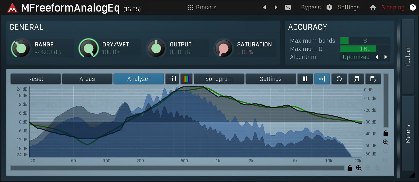
And thirdly, the equalizer may use parametric filters to try to emulate the frequency response curve that you have drawn. This is very complex technology and a disadvantage is that it probably won't match your response accurately, but at least it will show you the exact response. MFreeformAnalogEq is the only equalizer like this to my knowledge.
- Extremely flexible.
- What-you-see-is-what-you-get.
- May cause several audio problems due to FFT or the response isn't accurate.
- Not so fast to use, since editing graphs accurately may not be that easy.
- What you draw can actually sound bad.
- Higher CPU consumption.
FFT, the Fast Fourier transform
First let's learn some more theory. The Fourier transform converts a signal from time-domain to frequency-domain and back again. Each of the domains has its advantages and limitations, and this transform can allow you to create sonic miracles, but these miracles have severe flaws.
The trouble is, Fourier transform is only a theoretical approach and can never be performed in practice. The main reason is that it transforms analytical signals, not discrete sampled signals limited in time. Even if you could turn the entire earth into a giant supercomputer, you still wouldn't have enough power to process even a second of audio data using real perfect Fourier transform.
However, it was discovered a few centuries ago, that the same principle can be applied to the discrete signals that we use when processing audio. Unfortunately, it's not that simple. Because of the need for it to work in real time (and to lower the CPU requirements), the audio has to be processed in blocks. So if we have a block of 4,096 samples of time-domain data, to convert into some weird, spectral something, change it in some way and convert it back, there really isn't much information in those 4,096 samples. In fact it is the volume and phase of 2,048 frequencies. If we work at a 44,100 Hz sampling rate for example, which can therefore represent frequencies up to 22,050 Hz (look up 'Nyquist Frequency theorem' for more information), and we know only 2,048 of them, we are moving in steps of approximately 10 Hz. So we know the volume and phase of 0 Hz, 10 Hz, 20 Hz .. 80 Hz, 90 Hz etc. Now what if we have a sine wave at 85 Hz? The good news is, it doesn't just disappear. The bad news is, it will be 'spread' into the frequencies around it.
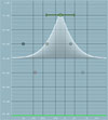
Here is an example of how a single frequency (specifically 100Hz) can look on a FFT analyzer with different settings (it should obviously be just a single vertical line):

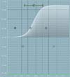
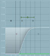
Yes, this really is a single sine wave! The 85 Hz sine wave is created by all these frequencies mixed together. You don't need to understand how it is created, it is just mathematics. Now think about what an equalizer does - it somehow transforms each of these frequencies, making them bigger or smaller. So imagine a 90 Hz 'ideal' low-pass filter. It simply removes everything above 90 Hz. Now we start to see the problem. Our 85 Hz sine wave is created using frequencies from say 50 Hz to 200 Hz. If we just remove everything above 90 Hz, this is the result:

This is NOT an 85 Hz wave anymore! Now envisage that there are hundreds of such frequencies in the signal! Our ideal low-pass filter is of course an extreme case, but more or less any filter type causes this problem. We can increase the block size to 8192 samples, which makes each step only 5 Hz. The hill in the analysis would look narrower, but that also increases latency, which may not be suitable. We can never solve this problem completely, we can only minimize it.
Since note frequencies are placed logarithmically (between 50 Hz and 100 Hz there are more than 12 semitones, but between 9000 Hz and 9050 Hz there is just one at most), so the FFT problem mostly affects bass notes. This is often called "poor bass resolution".
Another problem with FFT is that after processing each block, the audio signal shape is changed so it is not aligned with the previous or next blocks anymore. So the algorithms used must also supply some kind of overlapping and interpolation functions. Together with the high arithmetical complexity of FFT, this may introduce several artefacts.
Recently we tested an equalizer from a company claiming to have solved the poor bass resolution problem. It was done by increasing FFT size up to more than 100,000. Obviously, this led to high CPU consumption that made it unusable and created a latency of over one second! Consequently, when you changed something, it took more than a second to hear the results!
Conclusion about FFT:
- Very simple to develop.
- Extremely versatile.
- Poor bass resolution and other problems degrading sound quality.
- High arithmetical complexity degrading sound quality.
- Induces latency.
- Pretty high CPU consumption.
Linear-phase equalizers
The term linear-phase (LP) can cause some confusion so firstly, we will attempt to explain what it is and what it does. As we have discussed already, both hardware and software equalizers are made up of filters. These filters, by design, delay the frequencies passing through them by varying degrees which causes a change in the phase of the signal. These shifts in phase are designed to be kept as small as possible, so the filters are referred to as minimum-phase filters, Even though the shift in phase is small, the resulting waveform may have changed significantly because the mix of phase-shifted sine waves may be completely different from the original.
Linear-phase equalizers also introduce shifts in phase, but by the same number of samples for every frequency. So basically because all the frequencies are delayed by the same amount, it preserves the waveform but at the cost of introducing latency.
This means that it is not technically possible to have an LP equalizer in real time, without latency (called a zero-phase equalizer). However, it can be implemented offline, and since a well-developed LP equalizer should report its latency to the host, it in essence becomes a zero-phase equalizer, as the host should handle that reported latency using its "plugin delay compensation".
Linear-phase filters were originally designed for scientific purposes and not for audio at all. A heart rate monitor, for example, needs to detect the 'hills' in a signal (the heart beating) accurately, but it also intercepts physical signals containing lots of noise from other parts of the body. In order to focus on the relevant parts, it needs to remove everything else. This could be achieved using low-pass and high-pass filters, but if these filters also change the phase of the 'hills', the result will be inaccurate. Linear-phase filters preserve the phase and therefore these hills.
Usage in audio
If the brain ignores phase, then why do we need to use LP filters?
Your brain detects differences in phase between ears.
To find out, you can experiment yourself by creating two tracks with a sine
wave on each. Pan one track to the left, and the other to the right, then delay
one track and hit play. At first, what you hear may feel strange, but then it
should seem as if the audio source is at a different location. That's exactly
what the brain uses the phase for! The brain analyses the differences in phase
of the frequencies reaching both ears to determine the direction of the incoming
sound.
If you equalize both left and right channels at once, there is still no difference in phase between them, so it will sound the same. Equalize just one, and you will hear a change.
You may also want to avoid phase cancellation.
When you mix 2 tracks containing the same frequencies, they will be combined.
When a particular frequency has the same phase in both tracks, it becomes louder,
but if the phase difference is 180 degrees, then they will cancel each other
out and the frequency may even disappear.
The concern here is that we may feel
that we cannot mix without carefully analysing phase alignment. What if a guitar
track cancels out a piano for example? In reality, these phase cancellations
occur naturally all the time and their effect is usually unobtrusive. However,
care is usually needed if you are recording the same instrument using multiple
microphones, as there is a big chance that something may cancel out.
To illustrate this, if you want to record a really large orchestra in a church, you may place a few microphones at the front of the instruments and a few above the players etc. In most cases you need more than two microphones, otherwise it would either make some instruments much louder than the others (if you place them too close to the orchestra), or record too much ambience (if you place them further away). When approaching the mixing stage, there is a potential problem. Since every microphone was placed at a different distance from the players, the violin for example, will be delayed in each separate track. This delay is equal to a linear change in phase. When you mix the tracks, it may sound fine, but if the tracks are not in phase, it could become silent, or possibly sound otherwise unnatural when listening in stereo etc. If this is the case, you could spend a significant amount of time delaying all these tracks to overcome the problems. But if you then start equalizing the tracks to make the mix/ master sound good, you run the risk of distorting the phase again. In this scenario you may opt for a linear-phase equalizer.
But linear-phase equalizers also have drawbacks.
Change the bass frequencies a little on a bass drum track using an LP setting
on the MAutoEqualizer,
and it will degrade the punch of the drum. Switch it to normal mode and it sounds
fine again! Isn't one of the descriptions of linear-phase equalizers that they
do not 'smear transients'? Not always true according to this experiment.
The problem is so-called pre-ringing - try a rectangle waveform and process it with just about any parametric equalizer. You will see a long tail in the waveform after the original signal. This is called post-ringing and thanks to sound masking process in our brains this is almost inaudible. Less so for linear-phase equalizers, which also cause pre-ringing - a long tail "in front" of the rectangle.
Should you use an LP equalizer as your go-to standard equipment for
any recording?
Our advice would be no, but many people may disagree. It's all about finding
the right tool for the task. We have shown one example where there may be a
need for an LP equalizer, and another where using an LP equalizer is almost
excluded. Many engineers say that LP equalizers sound "sweeter". We probably
have to reach a traditional conclusion - if it sounds good, it is good ;).
There is however one area in which LP equalizers differ from other
equalizers - colourization.
Minimum phase equalizers basically sound the same and differ mostly in their
user interface. Linear-phase equalizer algorithms are generally much more complicated (unless FFT based)
and this can usually change or influence the sound. Whether or not this is a
good thing in a particular case, is up to you.
Linear-phase equalizer algorithms
We should mention LP equalizer algorithms, because this topic is both controversial and confusing, and it may just influence you in your choice.
1) FFT equalizers
If you are a developer, trust me, this is going to be your first choice. Because it is simple to implement, nothing more. Every good high-school student can use FFT to create a linear-phase equalizer. In fact, it is the simplest usage of FFT resynthesis in audio processing. If you have skipped the section about Fourier transform above, please go back and read it now.
You can check the FFT algorithm in MAutoEqualizer, which implements this method as a supplementary feature. It will probably sound the same, but try a peak filter in the bass frequencies and some surgical tweaking. You will soon realise, that something is just not right.
Please note that since analyzers are based on FFT, you will usually have to 'hear' the problems as they won't be visible on the analyzer displays.
2) FIR equalizers
FIR (finite-impulse response) filters are the very basics of filtering technology. They are simple to implement, and making them linear-phase is just as easy. Another great thing is that you can theoretically get any filter you want, you just need enough computing power and must be willing to accept induced latency. Therefore they are used a lot in scientific applications.
This is unfortunately not as useful to us. Too high a latency is unworkable and CPU power is usually very limited even today. So FIR filters are replaced by FFT using a simple trick, which makes them faster, but, gives them the same disadvantages the FFT equalizers have.
There are several graphical equalizers based on pure FIR filters. These may be pretty quick, and their latency more acceptable, however, they come with all of the disadvantages of graphical equalizers.
3) Bidirectional IIR equalizers
Most hi-end linear-phase equalizers are based on this method.
Most minimum phase parametric equalizers are based on IIR (infinite-impulse response) filters, which are basically simulations of analogue devices. These filters cannot be tweaked to give any response you want like in the way that FIR filters can, and you cannot just make them linear-phase. They are however extremely fast, and have a very high resolution, even in the bass spectrum.
Although you cannot have any phase response you want, there is a simple workaround. When you process the audio normally, you change the phase of several frequencies. If you then process the audio backwards (for example reverse the audio file and process again) using the same filter, it will cause an opposite change of phase. This essentially cancels out the previous phase change. Of course you can do this manually if you want to but this does add another stage to your work flow.
However, you cannot achieve this in real time, as the full audio file needs to be present, in order to start the reverse processing. You cannot just cut the audio into blocks and process each block separately either. So the goal is to find a way to handle this in real time. These algorithms are usually very sophisticated, and typically need lots of development. This is what makes the difference between equalizers.
In conclusion, well programmed bidirectional IIR LP equalizers provide the best audio quality, maximum resolution in low frequencies, lowest CPU requirements and typically the highest prices.